GVA Functional Areas
The GVA HMI is organised into functional areas that provide context-specific displays and controls for different vehicle operations.
Functional Area Overview
| Key | Area | Description |
|---|---|---|
| 1 | SA | Situational Awareness |
| 2 | WPN | Weapons |
| 3 | DEF | Defence |
| 4 | SYS | Systems |
| 5 | DRV | Driver |
| 6 | STR | Set To Role |
| 7 | COM | Communications |
| 8 | BMS | Battlespace Management |
Situational Awareness (SA)
The Situational Awareness functional area provides video and camera feeds with tactical overlays.
Single Camera View
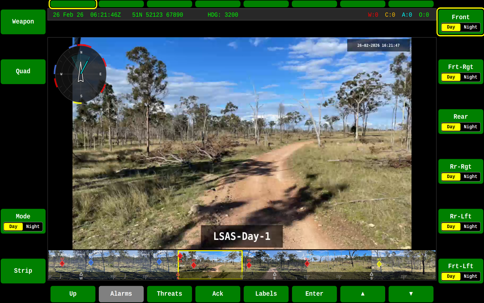
The SA screen can display a single camera feed with an information strip:
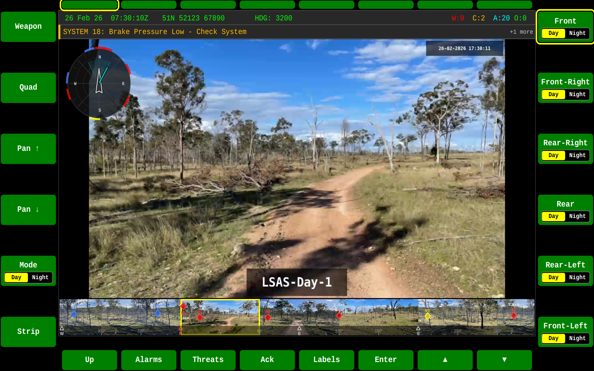
Camera with Strip Layout
The strip layout provides additional status information alongside the camera feed:
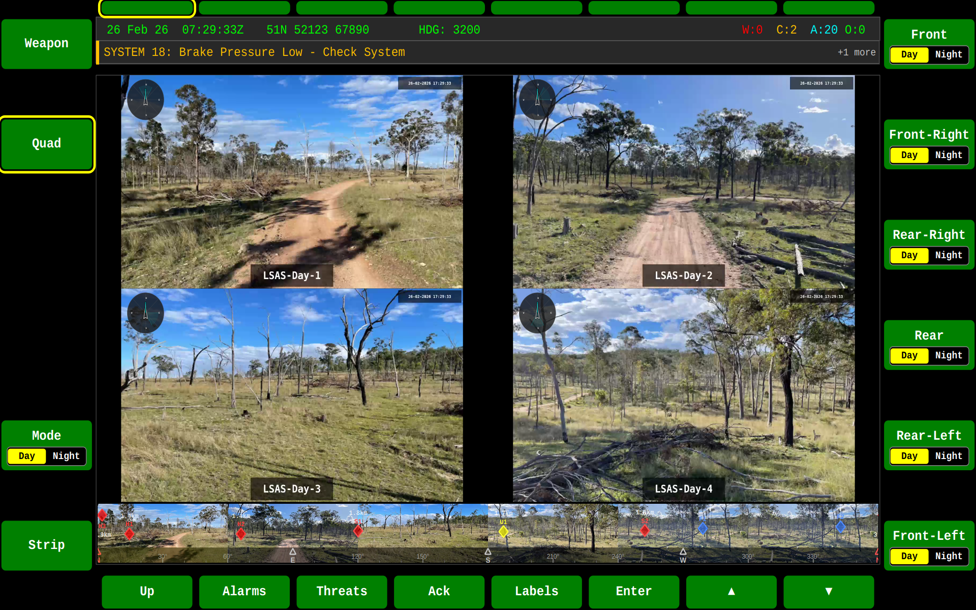
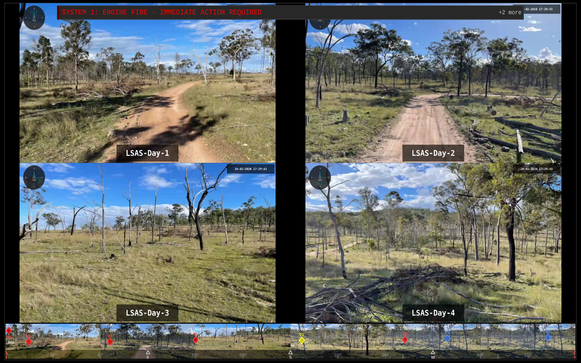
Quad Camera Views
Multiple camera feeds can be displayed simultaneously in quad layout:
Day Mode
Night Mode
Fullscreen
Defence (DEF)
The Defence functional area provides threat detection, classification, and tracking displays. It integrates with the DDS Battlespace Objects domain to present real-time threat information to the operator.
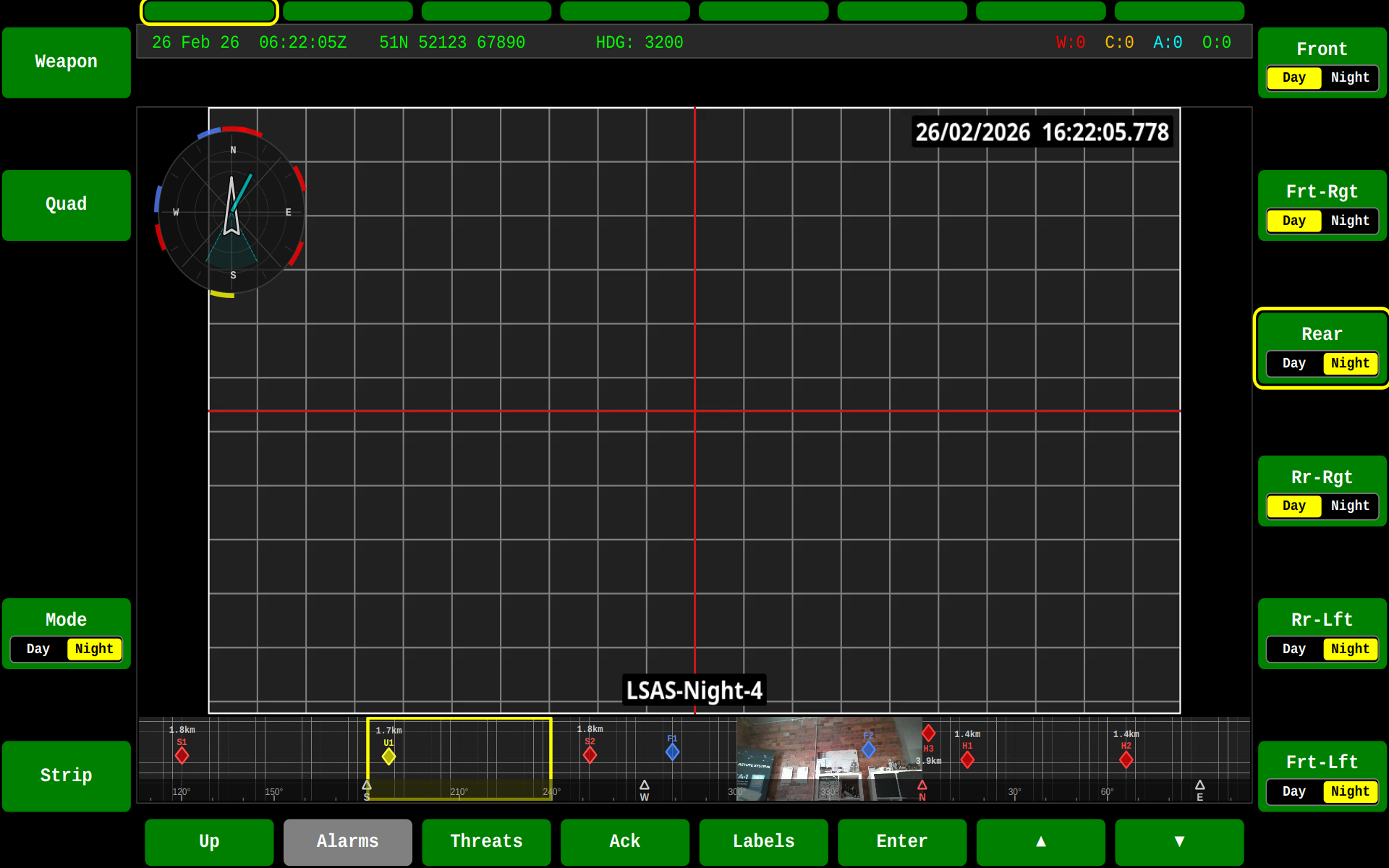
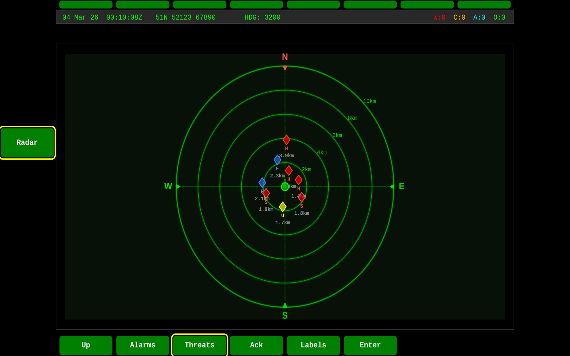
Radar View
The radar view is a top-down plan position indicator (PPI) centred on the vehicle. Threats are displayed as colour-coded diamond markers positioned by bearing and range:
The zoomed view provides greater detail for closer threats, toggled with F2:
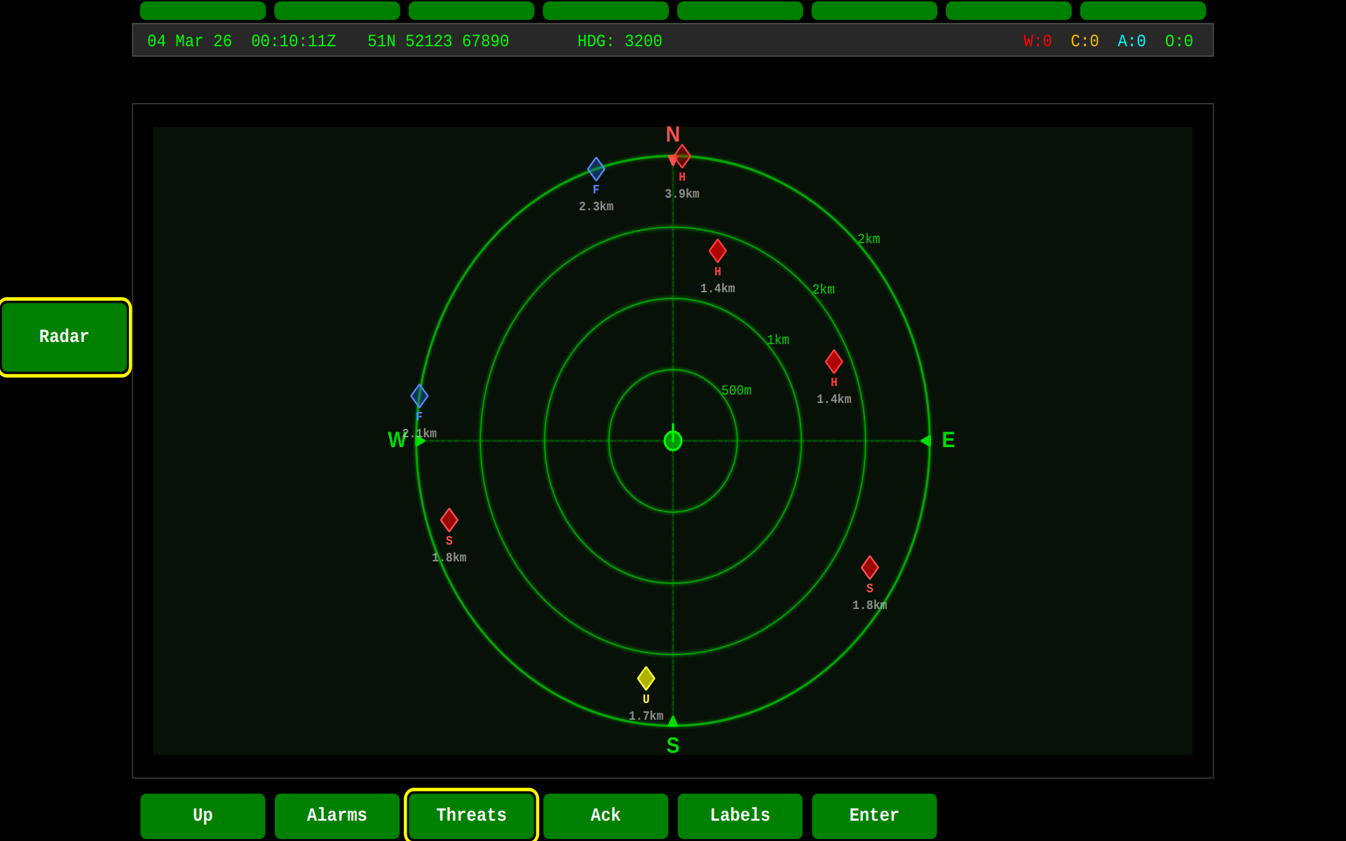
Radar features:
- Range rings at 2 km intervals (5 rings out to 10 km)
- N/S/E/W compass markers that rotate with vehicle heading
- Threat diamonds colour-coded by hostility:
- Red — Hostile
- Orange — Suspect
- Yellow — Unknown
- Green — Neutral
- Blue — Friendly
- Click-to-zoom toggle for close-range inspection
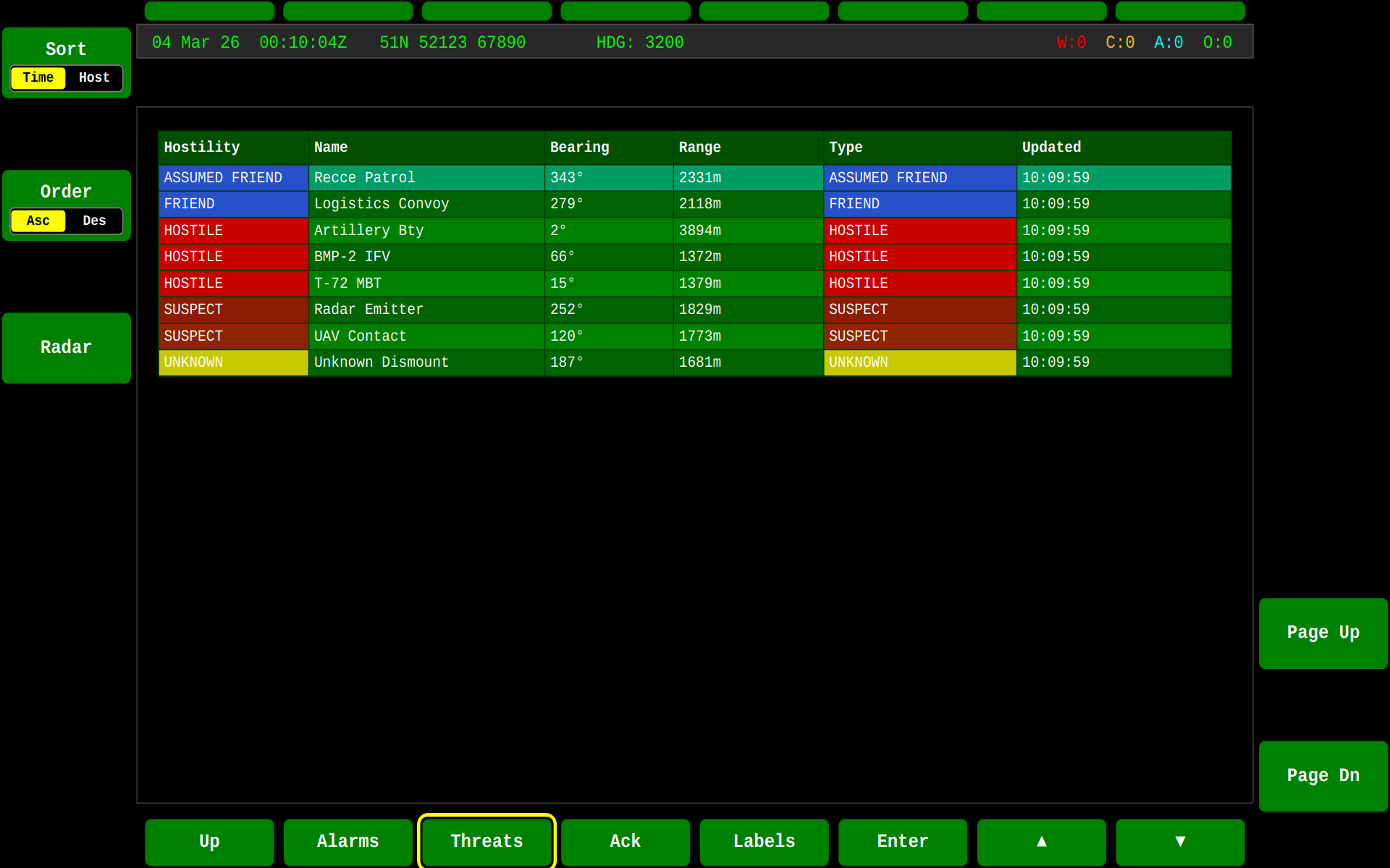
Threat Table
The tabular view lists all tracked battlespace objects with hostility classification, bearing, range, object type, and last update time:
LSAS Strip Integration
The LSAS (Local Situational Awareness System) strip shows six live camera thumbnails in a horizontally scrollable view with a 360° direction bar. When threats are present, diamond-shaped indicators are overlaid directly onto the camera thumbnails at the corresponding bearing. This provides immediate visual correlation between camera feeds and detected threats:
- Threat diamonds are positioned vertically by range (closer = lower, further = higher)
- Colour coding matches the radar view hostility scheme
- Labels show threat identifiers (e.g. "H1", "S2") and range in metres
- Indicators update in real time as threats move
The LSAS strip is toggled with F6 on the SA screen and supports day/night mode switching via F5.
Threat Lifecycle
Threats follow a DDS-driven lifecycle using the Battlespace Objects topics defined in DEF STAN 23-009 LDM:
| Stage | DDS Topic | Description |
|---|---|---|
| Detection | C_Battlespace_Object |
New object with hostility classification |
| Tracking | C_Object_Location |
Continuous position updates; bearing/range calculated from vehicle position |
| Reclassification | C_Battlespace_Object |
Hostility updated (e.g. Unknown → Hostile) |
| Removal | C_Battlespace_Object_CP_objectDeleted |
Object removed from all displays |
All threat displays — PPI overlay, DEF radar, threat table, and LSAS strip diamonds — update simultaneously from the same threat data source.
Systems (SYS)
The Systems functional area provides access to vehicle subsystem status and configuration.
ASLAV System View
Example of the Systems display showing ASLAV vehicle subsystem status:
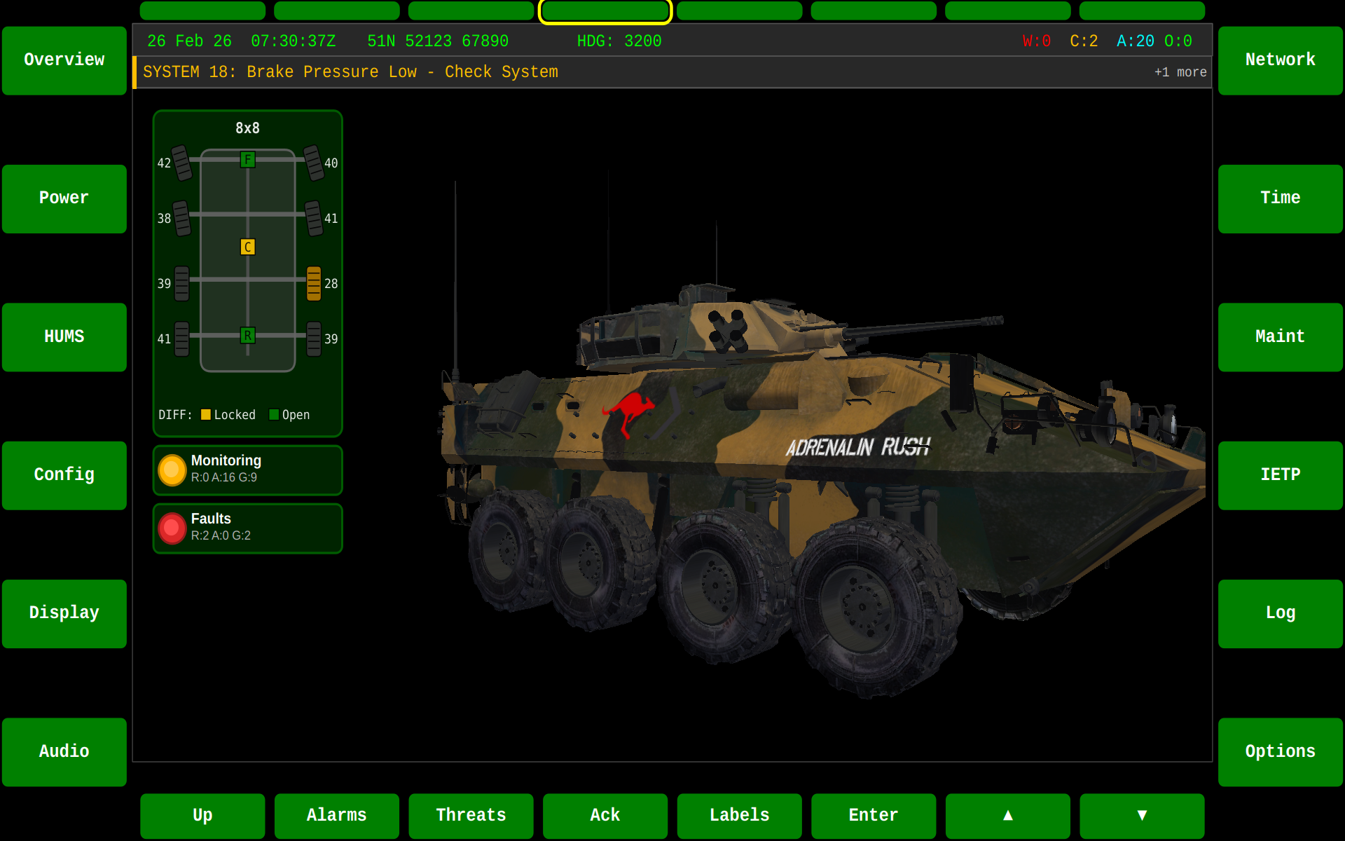
The Systems display shows:
- Subsystem health status
- Component connectivity
- Configuration parameters
- Diagnostic information
Driver (DRV)
The Driver functional area provides driving assistance and vehicle camera views.
Front Camera View
The Driver display can show front-facing camera feed for enhanced situational awareness:
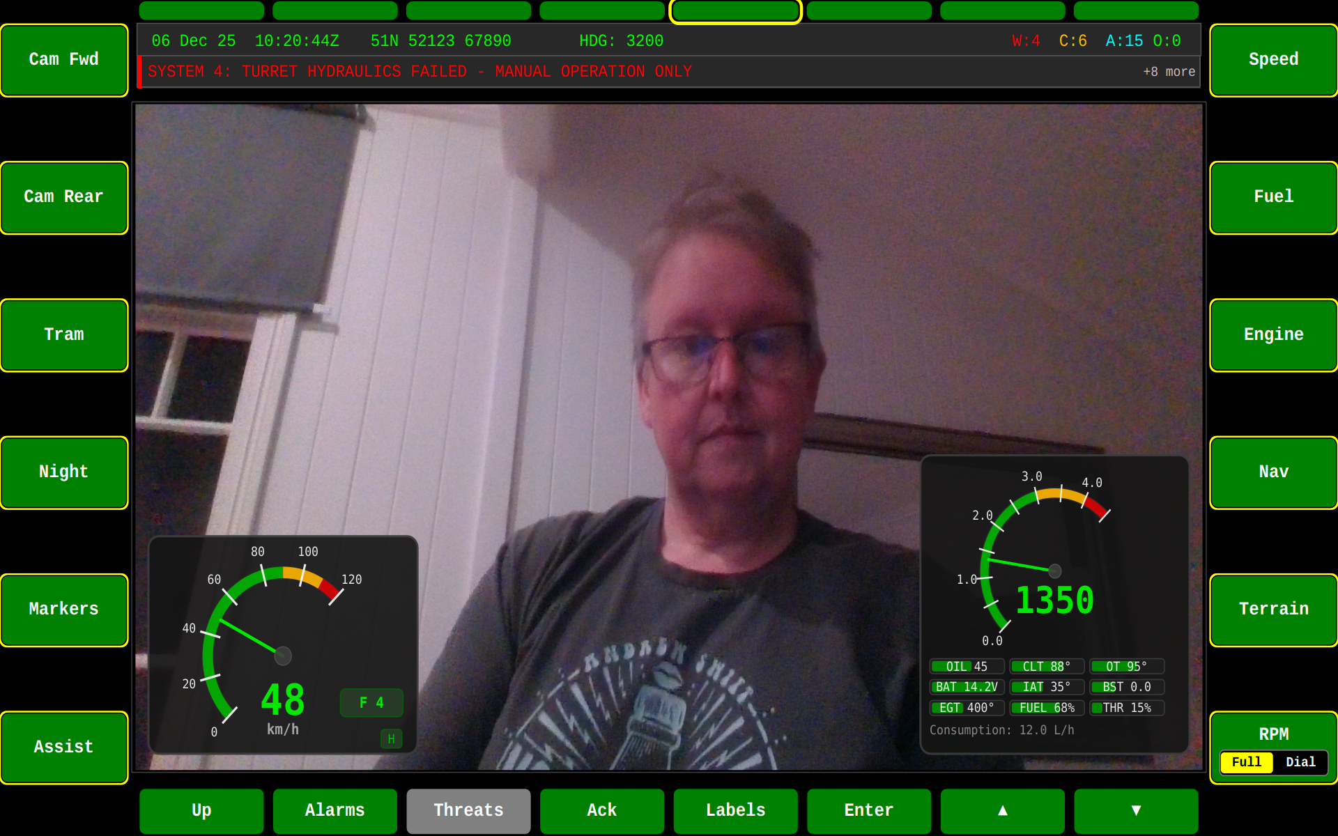
The Driver display supports:
- Front, rear, and side camera views
- Night vision / thermal imaging modes
- Picture-in-picture configurations
- Camera overlay controls
Switching Functional Areas
Use the function select buttons (typically 1-8) to switch between functional areas:
# From keyboard in development mode
1 - Situational Awareness
2 - Weapons
3 - Defence
4 - Systems
5 - Driver
6 - Set To Role
7 - Communications
8 - BMS
Or use the HMI's touchscreen soft keys to navigate between areas.